Non-reciprocal piezoelectric metamaterials with tunable mode shapes
 Amr Baz
- Mechanical Engineering Department, University of Maryland, College Park, MD, United States
The mode shapes of piezoelectric metamaterials are tuned by manipulating spatially the electrical boundary conditions of the piezo-elements, in a desired and controlled manner, in order to tailor the wave propagation characteristics through these metamaterials. The boundary conditions of the piezo-elements are controlled by using inductive shunting networks. With appropriate tuning and optimization of the spatial distribution of these inductive boundary conditions, it would be possible to alter the mode shape characteristics of the metamaterial in order to control the magnitude and direction of wave propagation. This enables also breaking the reciprocity characteristics of the metamaterial in a controlled manner. A finite element model (FEM) is developed to model the mode shape characteristics and the wave propagation in a one-dimensional piezo-metamaterial. The effect of various shunting strategies on the spatial control of the mode shapes, energy flow, and reciprocity characteristics of the piezo-metamaterial are investigated. The presented work lays down the foundation for two and three-dimensional metamaterial with tunable mode shape characteristics.
1 Introduction
Recently, the focus has been placed on the development of a wide variety of classes of non-reciprocal metamaterials (NMM) to control the magnitude and direction of wave propagation through these metamaterials. The basic concepts, the theoretical and experimental bases, as well as typical performance characteristics of these non-reciprocal systems are summarized in the concise account of Nassar et al. (2020) and Wang et al. (2018). The majority of the developed NMM are intended for use in critical applications such as acoustic diodes and topological insulators.
The approaches adopted to the break the reciprocity vary from simple passive approaches to the more imaginative active means. Distinct among the passive approaches are those including constitutive nonlinearity (Liang et al., 2009; Gu et al., 2016; Merkel et al., 2018; Petrover and Baz, 2020; Raval et al., 2020), momentum bias (Fleury et al., 2014; Liu et al., 2015; Liu et al., 2019; Wiederhold et al., 2019), and gyroscopic coupling (Attarzadeh et al., 2019). The performance characteristics of the passive NMM are enhanced by providing them with active control capabilities as proposed, for example, by Popa and Cummer (2014), Popa et al. (2015),Trainiti and Ruzzene (2016), Nasser et al. (2017), Baz 2018 and Baz 2019a), Yi et al. (2019), Karkar et al. (2019), Zhai et al. (2019) and Goldsberry et al., 2019 and Goldsberry et al., 2020. Other interesting active control approaches to break the reciprocity include the use of virtual gyroscopic controllers (Baz, 2018; Raval et al., 2021; Baz, 2022; Zhou and Baz, 2022) and by introducing a unique eigen-structure tuning controller (Baz, 2020a, Baz, 2020b and Baz, 2022; Zhou and Baz, 2021).Zhou and Baz, 2022
In the present paper, the theoretical bases for the breaking of the reciprocity are established for a special class of piezoelectric metamaterials. Such control of the reciprocity is achieved by manipulating spatially the electrical boundary conditions of the piezo-elements, in a desired and controlled manner by shaping the mode shape, in order to tailor the wave propagation characteristics through these metamaterials. The boundary conditions of the piezo-elements are controlled by using inductive shunting networks.
This work distinguishes itself from the work of Zheng et al. (2019) where piezoelectric bistable shunting networks are used to introduce nonlinearities and asymmetry along the wave propagation path. Such complexity in the control of the piezo-elements can introduce undesirable structural instabilities. Furthermore, the shunting networks are coupled, from one end, with hard-wired linear circuits and, from the other end, with short-circuits that make the reversibility of the reversal of the non-reciprocal wave propagation rather difficult to achieve.
In here, the control of the reciprocity is achieved using completely linear elements that can be programmable to ensure stable operation and enable reversable of the reciprocal behavior. Furthermore, the selection of the shunting elements has been based on solid finite element modeling coupled with optimal design procedures.
This paper is organized in five sections. In section 1, a brief introduction of the passive and active control approaches of non-reciprocity is presented and the concept of the nonreciprocal piezoelectric metamaterials with shaped eigen-vectors is outlined in Section 2. The finite element modeling (FEM) of the piezoelectric metamaterial when coupled with shunted electric networks is described in Section 3. Numerical examples are presented in Section 4 to demonstrate the merits and basic performance characteristics of the piezoelectric metamaterial with tunable mode shapes. The emphasis, in Section 4, is to demonstrate the effectiveness of the mode shape tuning on breaking the reciprocity. Finally, Section 5 summarizes the conclusions and possible recommendations for future studies.
2 Concept of the nonreciprocal metamaterial
In this section, the concept of the proposed piezoelectric nonreciprocal metamaterial (NMM) configuration consisting of an array of periodic system which consist of cells that are provided with shunted electric networks as shown in Figure 1A. The parameters of the shunted networks are tuned by appropriate assignment of the mode shapes (i.e., eigenvectors) of the entire assembly (Baz, 2018-Baz, 2022). Such an approach enables the spatial control of the energy flow along the metamaterial to achieve any desirable non-reciprocal characteristics.
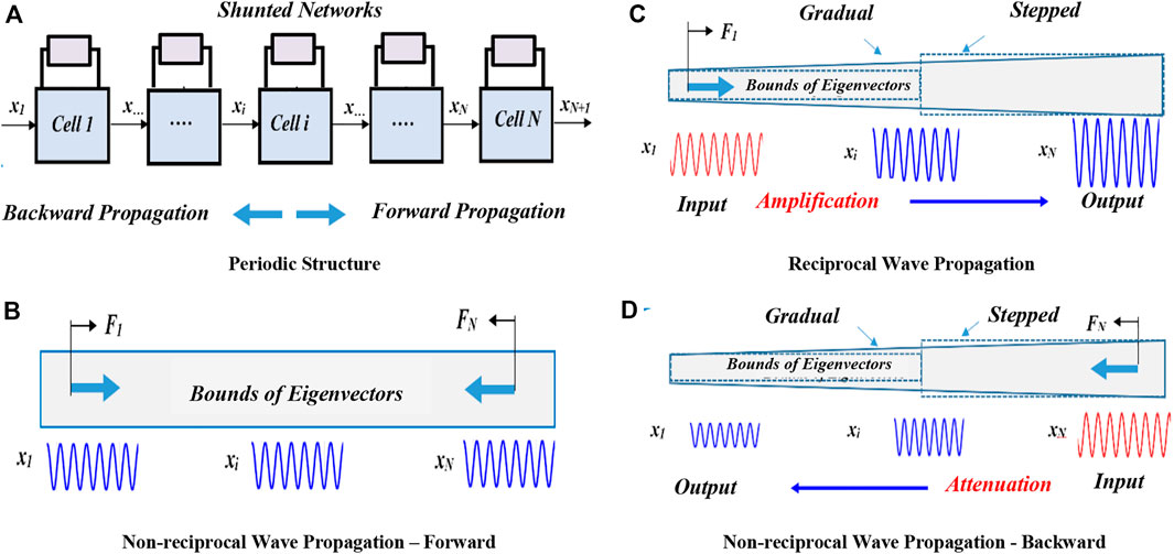
FIGURE 1. A schematic drawing of a 1D periodic dynamical system.
In Figure 1B, the upper bounds of the mode shapes (i.e., eigenvectors) of the un-shunted metamaterial assembly are displayed. The un-shunted system exhibits the conventional reciprocal behavior. But, shaping the bounds of the mode shapes (i.e., eigenvectors) of the shunted metamaterial assembly as shown in Figure 1C, the wave propagation along the forward direction can be amplified to acquire the desired profiles of the shaped mode shapes. Upon the reversal of the wave propagation direction as shown in Figure 1D, then the backward waves propagation will experience attenuation as imposed by the shaped mode shape profile. This generates a non-reciprocal wave propagation behavior which is completely controlled by tuning the parameters of the shunted network. In this manner, the extent and direction of the introduced non-reciprocity can be altered on demand.
3 Finite element modeling of the non-reciprocal piezoelectric metamaterials
The finite element model of the proposed piezoelectric metamaterial composite rod, shown in Figure 2A is developed in this section. The model describes the dynamics of a unit cell of the metamaterial as displayed in Figure 2B. The unit cell consists of a base structure with properties (ρr, Ar, Er) bonded to it a piezoelectric layer with properties (ρp, Ap, Ep) which is shunted by an inductive-capacitive (L-Ce) network. Note that ρi, Ai, and Ei denote the density, cross sectional area, and Young’s modulus of the ith layer where i = r and p which refer to base structure and piezo-layers, respectively.
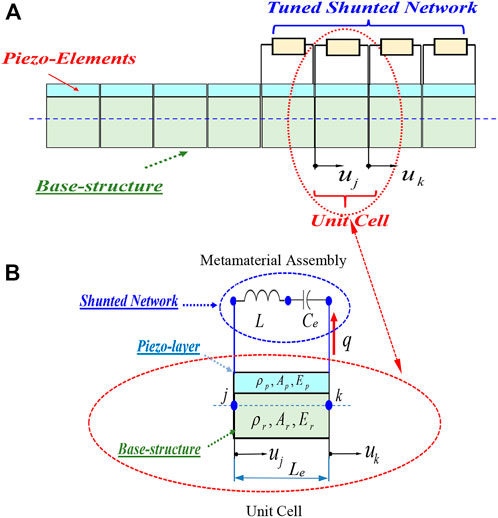
FIGURE 2. A schematic drawing of the piezoelectric composite metamaterial.
3.1 Constitutive equations of the piezoelectric layer
These equations are described by the following matrix form (IEEE, 1987):
where T1p, E3, S1, and D3 denote the stress, electric field, strain, and electric displacement, respectively with subscripts 1 and 3 define the longitudinal and across the thickness directions, respectively.
Also,
Equation 1 can be expanded to lead to:
3.2 Mass and stiffness matrices of the piezoelectric metamaterial cell
3.2.1 The kinetic energy
where ti and b are the thickness and width of the base structure and piezoelectric layer. Also, Le is the element length and u is the longitudinal deflection described in the finite element classical format:
with [N] and {Δ} define the interpolation matrix and the nodal deflection vector, respectively. For this one-dimensional metamaterial structure, it is assumed that a simple linear shape function is adequate to extract the interpolating matric [N]. The convergence accuracy is achieved by increasing the number of finite elements.
Combining Eqs 3, 4 leads to:
Where
3.2.2 The potential energy
In Eq. 6, the first term of the PE defines the energy associated with the structural component while the second term defines that of the electrical component. Substituting Eqs 2, 6 yields:
and
where
In Eq. 8, the first term of the PE defines the energy associated with the structural component, the second term defines that due to the coupling between the mechanical and electrical fields, while the third term relates to the energy of the electrical components. Also,
3.2.3 The virtual work by the external Loads and the shunted network (δW)
This work is given by:
where L and Ce are the shunting inductance and capacitance, respectively.
3.2.4 The Lagrange’s equations of motion
The Lagrange’s equations of motion governing the dynamics of the structural and electrical degrees of freedom are given by:
where
Eq. 11 can be rewritten in a compact dimensionless form, as indicated in the appendix by Eq. (A.5), as follows:
where
3.2.5 Condensation of The Lagrange’s equations of motion
The “Static Condensation” method is employed to condense the Lagrange’s Eq. 11 in order to retain only the structural degrees of freedom (DOF) as the primary DOF (Cammarata, et al., 2019). This condensation is achieved by expanding the second row of Eq. 12 using only the static components to yield:
This leads to:
Combining Eqs 12, 14 yields the following reduced-order model of the metamaterial cell:
where
The matrices of the unit cells are assembled yielding the overall equations of motion of the entire piezoelectric metamaterial assembly as follows:
The associated eigenvalue problem of the assembled Eq. 16 is given by:
where
3.2.6 Tuning of the parameters of the shunted network and the mode shapes
Figure 3 displays the flow chart of the tuning of the parameters of the shunted network and the mode shapes.
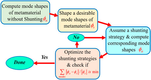
FIGURE 3. Flow chart of the tuning of the parameters of the shunted network and the mode shapes.
In the flow chart, the “shaped” or “desirable” mode shapes
where the entries of the scaling matrix S are selected to appropriately modify the un-shunted eigenvector ϕu such that S takes the following general form:
where the entries si’s (i =1,…, n ) are scaling factors of the different degrees of freedom of the structure that are selected to spatially reshape the ith eigenvector as desired.
Note that the “achievable” mode shapes
4 Numerical examples and performance characteristics of the non-reciprocal piezoelectric metamaterials
4.1 The unit cell
The geometrical and physical properties of the unit cell are selected, for illustrative purposes of the developed concepts, such that:
The metamaterial is divided into 10 elements and the optimal values of the shunted inductances
Such that and
Solution of the constrained optimization problem described in Eq. 20 is carried out using MATLAB Optimization toolbox.
The obtained optimal values of
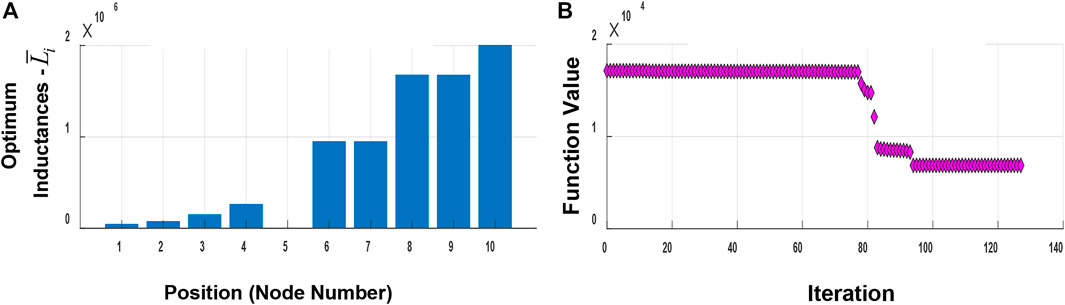
FIGURE 4. Optimal values of the dimensionless shunted inductances.
The optimization process aimed at shaping the original “unshunted” mode shapes ϕu (i.e., eigenvectors) as shown in Figure 5A. These mode shapes are bounded within boundaries that are uniform along the entire length of the meta-cell. These boundaries are then scaled and reshaped as shown in Figure 5B to achieve desirable profiles ϕs similar to those displayed in Figures 1A,B. These scaled boundaries are obtained by selecting the scaling factors si such that:
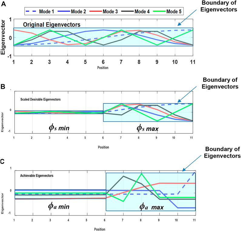
FIGURE 5. Comparison between the original, desirable, and achievable mode shapes (i.e., eigenvectors).
With such scaling factors, the targeted “scaled” or “desirable” profiles of the eigenvectors are displayed in Figure 5B. This scaling is intended to magnify the waves propagating along the forward direction while it is expected to attenuate the propagation along the backward direction.
The optimization process attempts to place the shunting inductances along the metamaterial in order to generate achievable mode shapes ϕa (i.e., eigenvectors) as close as possible to the desired mode shapes ϕs by minimizing the gap between ϕs and ϕa. The result of this optimization process yields the eigenmode profiles shown in Figure 5C.
The displayed mode shape profiles are obtained with the optimal inductances listed in Table 1.
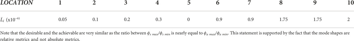
TABLE 1. Values of the optimal shunting inductances.
Figure 6 displays the transmitted waves in decibels (
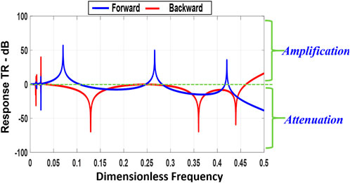
FIGURE 6. The transmitted waves during forward and backward propagations.
The effect of shaping the mode shapes has been illustrated further by considering the spatial distribution of the wave energy along the optimally shunted piezoelectric metamaterial when it is subjected to excitations at different frequencies.
Figures 7A–C display these characteristics when the excitations are carried out at the first, second, and third modes of vibration of the metamaterial. The figures reinforce the results displayed in Figure 6 indicating that the proposed modal tuning approach has produced significant amplification during forward propagation and equally considerable attenuation during the backward propagation for all the considered modes and over the entire structure of the metamaterial.
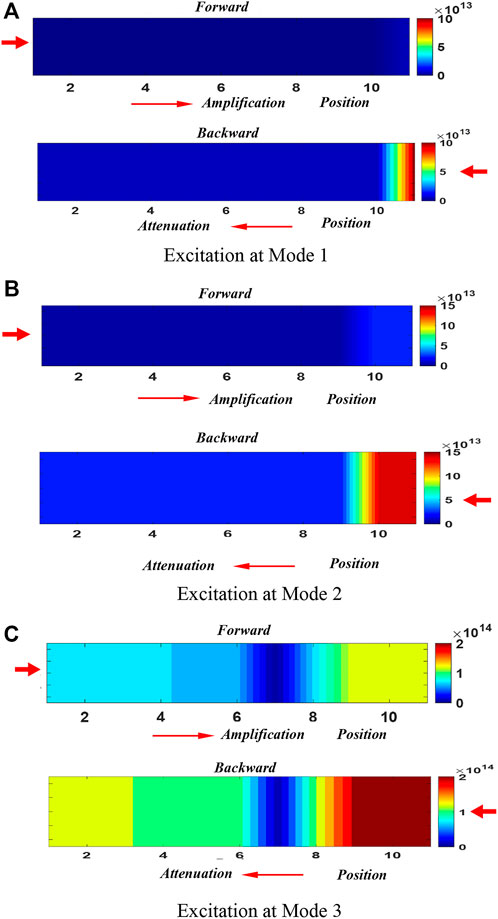
FIGURE 7. Amplification during forward propagation and attenuation during backward propagation at different excitation frequencies.
In other words, the displayed results emphasize the potential of shaping the mode shape in achieving non-reciprocal behavior both spatially and over a wide frequency bandwidth.
5 Conclusion
This paper has presented a finite element modelling approach to demonstrate the effectiveness of shaping the mode shapes of piezoelectric metamaterials, in a controlled manner, as an effective means for controlling the magnitude and direction of wave propagation along this class of metamaterial. With such capabilities, it has been shown that this approach enables breaking the reciprocity characteristics of the metamaterial, in an attempt, to generate a class of acoustic diodes.
A finite element model (FEM) is developed to model the mode shape characteristics and the wave propagation in a one-dimensional piezo-metamaterial. The effect of various shunting strategies on the spatial control of the mode shapes, energy flow, and reciprocity characteristics of the piezo-metamaterial are investigated.
Work is now in progress to validate the proposed modal tuning approach experimentally. The presented work lays down the foundation for two and three-dimensional metamaterial with tunable mode shape characteristics.
Data availability statement
The raw data supporting the conclusions of this article will be made available by the authors, without undue reservation.
Author contributions
Conceptualization, methodology, software, formal analysis, investigation, resources, data curation, writing—original draft preparation, writing—review and editing, visualization, and agreement to the published version of the manuscript by AB.
Conflict of interest
The authors declare that the research was conducted in the absence of any commercial or financial relationships that could be construed as a potential conflict of interest.
Publisher’s note
All claims expressed in this article are solely those of the authors and do not necessarily represent those of their affiliated organizations, or those of the publisher, the editors and the reviewers. Any product that may be evaluated in this article, or claim that may be made by its manufacturer, is not guaranteed or endorsed by the publisher.
References
Alzaher, H., and Tasadduq, N. (2007) “CMOS digitally programmable inductance”. IEEE, 2006. ICM '06. International Conference on Microelectronics, Dhahran. IEEE. Saudi Arabia. December 2006. 16–19. doi:10.1109/ICM.2006.373286
Attarzadeh, M. A., Maleki, S., Crassidis, J. L., and Nouh, M. (2019). Non-reciprocal wave phenomena in energy self-reliant gyric metamaterials. J. Acoust. Soc. Am. 146, 789–801. doi:10.1121/1.5114916
Baz, A. (2018). Active nonreciprocal acoustic metamaterials using a switching controller. J. Acoust. Soc. Am. 143 (3), 1376–1384. doi:10.1121/1.5026510
Baz, A. (2020a). Active nonreciprocal metamaterial using an eigen-structure assignment control strategy. J. Acoust. Soc. Am. 147 (4), 2656–2669. doi:10.1121/10.0001157
Baz, A. (2020b). Active synthesis of a gyroscopic-nonreciprocal acoustic metamaterial. J. Acoust. Soc. Am. 148 (3), 1271–1288. doi:10.1121/10.0001815
Baz, A. (2022). Breaking the reciprocity in acoustic metamaterials by active eigen-structure control strategy. J. Vib. Acoust. 144 (4), 041009. doi:10.1115/1.4053587
Baz, A. (2019b) “Nonreciprocal metamaterial with programmable nonlinear virtual resistors”. J. Acoust. Soc. Am. 145 (3), pp:1686, doi:10.1121/1.5101181
Cammarata, A., Sinatra, R., and Maddio, P. D. (2019). Static condensation method for the reduced dynamic modeling of mechanisms and structures. Arch. Appl. Mech. 89, 2033–2051. doi:10.1007/s00419-019-01560-x
Fleury, R., Sounas, D. L., Sieck, C. F., Haberman, M. R., and Alù, A. (2014). Sound isolation and giant linear nonreciprocity in a compact acoustic circulator. Science 343, 516–519. doi:10.1126/science.1246957
Goldsberry, B. M., Wallen, S. P., and Haberman, M. R. (2020). Nonreciprocal vibrations of finite elastic structures with spatiotemporally modulated material properties. Phys. Rev. B 102 (1), 014312. doi:10.1103/physrevb.102.014312
Goldsberry, B. M., Wallen, S. P., and Haberman, M. R. (2019). Non-reciprocal wave propagation in mechanically-modulated continuous elastic metamaterials. J. Acoust. Soc. Am. 146 (1), 782–788. doi:10.1121/1.5115019
Gu, Z.-M., Hu, J., Liang, B., Zou, X.-Y., and Cheng, J.-C. (2016), “Broadband non-reciprocal transmission of sound with invariant frequency”. Sci. Rep., 6, 19824, doi:10.1038/srep19824
IEEE (1987). IEEEStandard on piezoelectricity ANSI/IEEE std. 176-1987. IEEE. doi:10.1109/IEEESTD.1988.79638
Karkar, S., De Bono, E., Collet, M., Matten, G., Ouisse, M., and Rive, E. (2019). Broadband nonreciprocal acoustic propagation using programmable boundary conditions: From analytical modeling to experimental implementation. Phys. Rev. Appl. 12, 054033. doi:10.1103/physrevapplied.12.054033
Liang, B., Yuan, B., and Cheng, J. C. (2009). Acoustic diode: Rectification of acoustic energy flux in one-dimensional systems. Phys. Rev. Lett. 103, 104301. doi:10.1103/physrevlett.103.104301
Liu, C., Du, Z. L., Sun, Z., Gao, H. J., and Guo, X. (2015). Frequency-preserved acoustic diode model with high forward power-transmission rate. Phys. Rev. Appl. 3, 064014. doi:10.1103/physrevapplied.3.064014
Liu, X., Cai, X., Guo, Q., and Yang, J. (2019). Robust nonreciprocal acoustic propagation in a compact acoustic circulator empowered by natural convection. New J. Phys. 21, 053001. doi:10.1088/1367-2630/ab1bb7
Merkel, A., Willatzen, M., and Christensen, J. (2018). Dynamic nonreciprocity in loss-compensated piezophononic media. Phys. Rev. Appl. 9, 034033. doi:10.1103/physrevapplied.9.034033
Nassar, H., Hussein, M., Yousefzadeh, B., Fleury, R., Ruzzene, M., Alù, A., et al. (2020). Nonreciprocity in acoustic and elastic materials. Nat. Rev. Mat. 5 (9), 667–685. doi:10.1038/s41578-020-0206-0
Nassar, H., Xu, X. C., Norris, A. N., and Huang, G. L. (2017). Modulated phononic crystals: Nonreciprocal wave propagation and Willis materials. J. Mech. Phys. Solids 101, 10–29. doi:10.1016/j.jmps.2017.01.010
Petrover, K., and Baz, A. (2020). Finite element modeling of one-dimensional nonreciprocal acoustic metamaterial with anti-parallel diodes. J. Acoust. Soc. Am. 148 (1), 334–346. doi:10.1121/10.0001625
Popa, B.-I., and Cummer, S. A. (2014). Non-reciprocal and highly nonlinear active acoustic metamaterials. Nat. Commun. 5, 3398. doi:10.1038/ncomms4398
Popa, B.-I., Shinde, D., Konneker, A., and Cummer, S. A. (2015). Active acoustic metamaterials reconfigurable in real-time. Phys. Rev. B 91, 220303. doi:10.1103/physrevb.91.220303
Raval, S., Petrover, K., and Baz, A. (2020). Experimental characterization of a one-dimensional nonreciprocal acoustic metamaterial with anti-parallel diodes. J. Appl. Phys. 128, 074502. doi:10.1063/5.0019896
Raval, S., Zhou, H., and Baz, A. (2021). Experimental implementation of an active synthesis of a gyroscopic-nonreciprocal acoustic metamaterial. J. Appl. Phys. 129, 074501. doi:10.1063/5.0036754
Trainiti, G., and Ruzzene, M. (2016). Non-reciprocal elastic wave propagation in spatiotemporal periodic structures. New J. Phys. 18, 083047. doi:10.1088/1367-2630/18/8/083047
Wang, Y., Yousefzadeh, B., Chen, H., Nassar, H., Huang, G., and Daraio, C. (2018). Observation of nonreciprocal wave propagation in a dynamic phononic lattice. Phys. Rev. Lett. 121, 194301. doi:10.1103/physrevlett.121.194301
Wiederhold, C. P., Sounas, D. L., and Alù, A. (2019). Nonreciprocal acoustic propagation and leaky-wave radiation in a waveguide with flow. J. Acoust. Soc. Am. 146, 802–809. doi:10.1121/1.5115018
Yi, K., Ouisse, M., Sadoulet, E., and Matten, G. (2019). Active metamaterials with broadband controllable stiffness for tunable band gaps and non-reciprocal wave propagation. Smart Mat. Struct. 28 (6), 065025. doi:10.1088/1361-665x/ab19dc
Zhai, Y., Kwon, H., and Popa, B. (2019). Active Willis metamaterials for ultra-compact non-reciprocal linear acoustic devices. Phys. Rev. B 99, 220301. doi:10.1103/physrevb.99.220301
Zheng, Y., Wu, Z., Zhang, X., and Wang, K. W. (2019). A piezo-metastructure with bistable circuit shunts for adaptive nonreciprocal wave transmission. Smart Mat. Struct. 28, 045005. doi:10.1088/1361-665x/ab083c
Zhou, H., and Baz, A. (2022). A simple configuration of an actively synthesized gyroscopic-nonreciprocal acoustic metamaterial. J. Vib. Acoust. 145. doi:10.1115/1.4055103
Zhou, H., and Baz, A. (2022). Active nonreciprocal metamaterial using a spatiotemporal modulation control strategy. Appl. Phys. Lett. 121, 061701. doi:10.1063/5.0100804
Zhou, H., and Baz, A. (2021). Experimental realization of an active non-reciprocal metamaterial using an eigen-structure assignment control strategy. J. Acoust. Soc. Am. 150 (2), 1092–1107. doi:10.1121/10.0005874
Appendix A: Dimensionless form of the Equations of Motion
The equations of motion as defined by Eq. 11 can be cast in a dimensionless form by assuming the following dimensionless variables:
Also, the stiffness and mass matrices are rewritten as:
and
Let
Substituting Eqs. (A.1–A.4) into Eq. 10, it reduces to:
Where
Note that
Nomenclature
A cross sectional area
b width of piezoelectric element
Cei shunting capacitance of the ith element
d31 piezo-strain constant
D3 Electrical displacement along direction 3
E3 Electrical field due to voltage along direction 3
Ep,r Young’s modulus of the piezo and structural layers, respectively
Fi external force acting on the ith cell
h31 piezoelectric constant
[Ks] structural stiffness matrix
KE Kinetic energy
Le length of each cell
Li the shunting inductance of the ith element
[Mp,r] mass matrices of the piezo and structural layers
[M] the total mass matrix
{N} interpolation matrix
n number of finite elements
PE potential energy
Qi electric charge of the ith shunted networks
R transformation matrix between the structural deflections and electric charge
S1 strain along direction 1
tp,r thickness of the piezo and structural layers, respectively
T transformation matrix between the structural deflections and the state vector
T1 stress in direction 1
u axial deflection
v volume x the x coordinate
{X} the vector of state-variables
Greek symbols
{Δi} vector of nodal deflections of the ith element.
ρp,r density of the piezo and structural layers, respectively
{ϕi} the ith eigenvector (n
{ϕai} the achievable ith eigenvector (n
{ϕsi} the desired ith eigenvector (n
ωn natural frequency
Keywords: piezoelectric metamaterial, tunable mode shapes, nonreciprocal behavior, finite element analysis, shunted inductive networks
Citation: Baz A (2022) Non-reciprocal piezoelectric metamaterials with tunable mode shapes. Front. Mech. Eng 8:1042727. doi: 10.3389/fmech.2022.1042727
Received: 12 September 2022; Accepted: 09 November 2022;
Published: 29 November 2022.
Edited by:
Chitaranjan Pany, Vikram Sarabhai Space Centre, IndiaReviewed by:
Xiao-Dong Yang, Beijing University of Technology, ChinaPatrick Andrew Dorin, University of Michigan, United States
Copyright © 2022 Baz. This is an open-access article distributed under the terms of the Creative Commons Attribution License (CC BY). The use, distribution or reproduction in other forums is permitted, provided the original author(s) and the copyright owner(s) are credited and that the original publication in this journal is cited, in accordance with accepted academic practice. No use, distribution or reproduction is permitted which does not comply with these terms.
*Correspondence: Amr Baz, [email protected]