Design engineering a walking robotic manipulator for in-space assembly missions
 Manu Harikrishnan Nair
 Mini Chakravarthini Rai
 Mithun Poozhiyil
- Lincoln Centre for Autonomous Systems, University of Lincoln, Lincoln, United Kingdom
In-Space Services aim to introduce sustainable futuristic technology to support the current and growing orbital ecosystem. As the scale of space missions grows, there is a need for more extensive infrastructures in orbit. In-Space Assembly missions would hold one of the key responsibilities in meeting the increasing demand. In the forthcoming decades, newer infrastructures in the Earth’s orbits, which are much more advanced than the International Space Station are needed for in-situ manufacturing, servicing, and astronomical and observational stations. The prospect of in-orbit commissioning a Large Aperture Space Telescope (LAST) has fuelled scientific and commercial interests in deep-space astronomy and Earth Observation. However, the in-situ assembly of such large-scale, high-value assets in extreme environments, like space, is highly challenging and requires advanced robotic solutions. This paper introduces an innovative dexterous walking robotic system for in-orbit assembly missions and considers the Large Aperture Space Telescope system with an aperture of 25 m as the use case. The top-level assembly requirements are identified with a deep insight into the critical functionalities and challenges to overcome while assembling the modular LAST. The design and sizing of an End-over-end Walking Robot (E-Walker) are discussed based on the design of the LAST and the specifications of the spacecraft platform. The E-Walker’s detailed design engineering includes the structural finite element analysis results for space and earth-analogue design and the corresponding actuator selection methods. Results of the modal analysis demonstrate the deflections in the E-Walker links and end-effector in the open-loop due to the extremities present in the space environment. The design and structural analysis of E-Walker’s scaled-down prototype is also presented to showcase its feasibility in supporting both in-orbit and terrestrial activities requiring robotic capabilities over an enhanced workspace. Further, the mission concept of operations is presented based on two E-Walkers that carry out the assembly of the mirror modules. The mission discussed was shortlisted after conducting an extensive trade-off study in the literature. Simulated results prove the dual E-Walker robotic system’s efficacy for accomplishing complex in-situ assembly operations through task-sharing.
Introduction
The evolution of robotics and artificial intelligence has revolutionised state-of-the-art space systems. Robotics, Automation and Autonomous Systems (RAAS) solutions have helped the space community conduct ground-breaking research in various planetary missions and on the International Space Station (ISS). Building upon these substantial achievements, the next few decades would unfold new chapters in orbital missions. Over the years, Extra-Vehicular Activities (EVA) have proven beneficial for servicing and maintenance missions on the ISS (Culbertson 2003). The installation of corrective optics on the Hubble Space Telescope (HST) is another explicit example of the success of EVA (Burrows 1991). However, the unfavourable space environment constantly risks EVA operations (Thirsk et al., 2009; Fazekas 2020). With future missions involving large-scale high-value infrastructures, assembly and maintenance would be much beyond human capabilities, requiring autonomous robots. Advancements in RAAS have resulted in a paradigm shift in space exploration as it would facilitate a multitude of In-Space services. In support of the plans to be a dominant candidate in the In Orbit Services and Manufacturing (IOSM) market, the UK Space Agency, along with multiple enterprises, are in plans to invest in relevant futuristic space technologies (Catapult 2020). In-Space services can facilitate numerous missions such as manufacturing, assembly, servicing, debris removal, astronomy, and Earth Observation (EO), to list a few (Alondra Nelson et al., 2022). Amongst the innumerable tasks which In-Space services can expedite, this paper focuses on assembling a Large Aperture Space Telescope (LAST) in orbit. LAST would promote a series of astronomical and EO missions (Baiocchi and Stahl 2009, Catapult 2020).
The move towards LAST commenced ever since the successful launch of the HST. Launched in 1990, the HST with a
This paper presents an updated design of the E-Walker for efficiently assembling a 25 m LAST in orbit. Initially, this paper elicits the top-level assembly requirements of LAST, the robotic system and the spacecraft platform. To meet the mission requirements, a seven Degrees-of-Freedom (DoF) fully dexterous E-Walker is introduced. The E-Walker draws inspiration from the Canadarm2 and the European Robotic Arm (ERA) on the ISS. The two links of the Canadarm2 are separated by a joint offset in the elbow, making it complicated for the robot arm to walk around connector ports placed in a straight line. On the other hand, the ERA has both its links attached to the side of its elbow joint, limiting the complete rotation of its the elbow joint like the Canadarm2 to an end-to-end motion. In comparison to Canadarm2 and ERA, the E-Walker has both its links in line about its elbow joint, allowing it to walk end-over-end like Canadarm2 without an offset. Either end of the E-Walker is equipped with a Latching End-Effector (LEE) to latch onto the static connector ports on LAST and the spacecraft platform. The proposed E-Walker’s redundant design and mobility features offer access to a much larger workspace than conventional fixed-to-base robotic manipulators. Also, the LAST design presented can be considered as a baseline for futuristic LAST designs, which can be scaled up for PMs up to 100 m aperture.
An in-depth design engineering exercise has been carried out for the E-Walker according to the system and mission requirements for 1) optimising the link and LEE parameters 2) actuator selection. Initially, different link shapes of a given link length were compared to analyse the mass and area moment of inertia. Thereafter, to evaluate deflection, stress and strain, and open-loop performance under external disturbances in orbit, Finite Element Analysis (FEA) was carried out for the E-Walker components through Static Structural Analysis (SSA) and Modal analysis. The torque requirements for joint actuators were obtained using E-Walker’s dynamic equation formulation, which eventually helped in selecting the electrical actuators for the system. Additionally, a scaled-down prototype for the Earth-analogue testing is introduced, which underwent a similar FEA analysis. The E-Walker prototyping work is now in progress at the University of Lincoln; therefore, the experimental verification and validation will be published separately. Figure 1 presents an overview of various applications of the E-Walker along with its configuration. Finally, this paper discusses a potential mission concept of operations (ConOps) to carry out a sequential assembly of the 25 m LAST. The presented mission concept is chosen based on an extensive feasibility study carried out in (Nair et al., 2020b). The ConOps utilise two E-Walkers to assemble the PM, showcasing the extensive cooperative task-sharing capabilities of a dual robotic system, much required in futuristic robotic space missions.
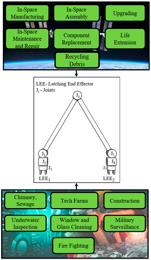
FIGURE 1. E-Walker applications and configuration.
The rest of the paper is organised into five sections. Top-level assembly requirements discusses the LAST mission’s top-level assembly requirements, including the robot and spacecraft system requirements. The Space grade E-Walker’s extensive design engineering is presented in End-over-end walking robot, where the full-scale system is optimised and analysed using SSA and Modal analysis under microgravity conditions. E-walker scaled-down Earth analogue design introduces the scaled-down Earth-analogue E-Walker prototype design. Mission concept of operations discusses a mission concept involving a dual E-Walker system to carry out the assembly. A flowchart is presented to depict the execution of this mission. In Conclusion and future research, the main inferences are covered, including an insight into planned experimental testing and further research.
Top-level assembly requirements
The top-level system architecture of the
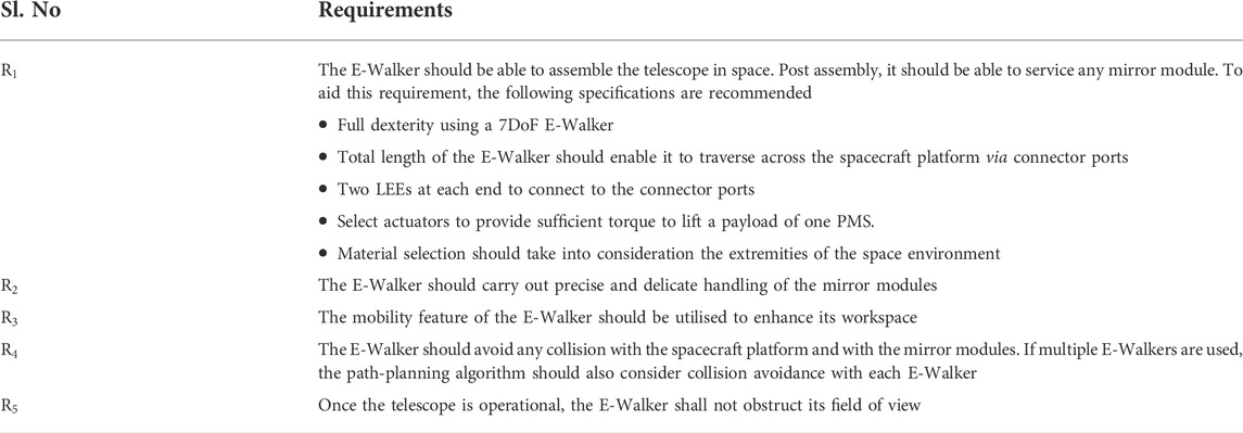
TABLE 1. Top-level requirement list for E-Walker.
Figure 2 illustrates the system architecture of the modular
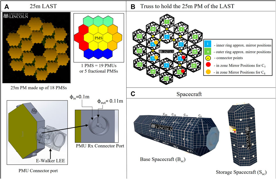
FIGURE 2. Top-level mission architecture (A) 25m last (B) truss; (C) Bsc and Ssc.
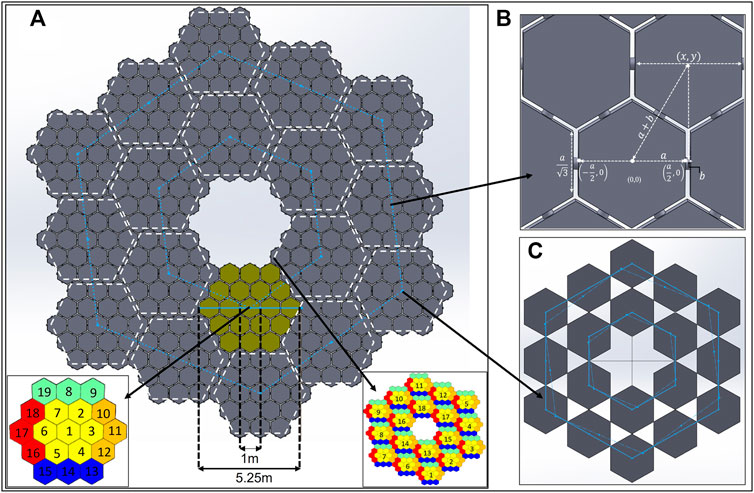
FIGURE 3. 25 m PM and Truss (A) PM Design; (B) PMU-PMU distance; (C) Position of Truss Connectors.
Figure 2A shows a close-up view of the PMU connector’s dimensions and design. Based on the assembly sequencing, the E-Walker would be provided with the information on the available connector ports to which it can latch on to. Understandably, the connector ports connected to other PMU ports should be left free. In addition to the Rx and Tx connectors on the sides of the PMU’s hexagonal backplate, there exists a Tx connector on the back side of every PMU1 of a PMS (Txb connector), which gets connected to an Rx connector of the Truss. As a result, there would be
Spacecraft platform requirements
The spacecraft platform comprises the Truss element, Base Spacecraft (Bsc) and a Storage Spacecraft (Ssc). The requirements associated with the platform are elicited below:
Truss requirements
The truss is built using
Establishing the importance of the in-zone mirror positions is necessary to carry out a safe and efficient assembly. These are positions on the truss that can be considered the adjacent mirror positions of any truss connector port. The red and orange circles, in Figure 2B indicate the in-zone mirror positions for the truss connector ports
Base spacecraft and storage spacecraft requirements
The adequate number of connector ports on the Bsc, Ssc and truss would help the E-Walker easily access the entire system (Figures 2B,C). Figure 4 shows the dimension of the Bsc and its grapple fixtures. As shown in this figure, the state-of-the-art design of current three-pin grapple fixtures on board the ISS to support Canadarm2 and ERA is utilised in this paper. These Power and Data Grapple Fixtures (PDGF) have a flat base plate, a small grapple shaft or pin with a ball on the top and three ramped bars around them to provide additional rotational stability post grapple. In addition, there exist four data and power cable ports and a target pin for the robotic arm to position itself using the camera on-board. To latch on to these fixtures, the Canadarm2 and the ERA have a Latching End-Effector on it is either end. The LEE features a carriage with a rotating ring inside it. The ring incorporates three snare wires, such that when the ring rotates, it closes the snare to lock itself onto the grapple pin, retracting the carriage to latch itself to the spacecraft. Similar PDGF and LEE configurations are designed for the spacecraft platform enabling the E-Walker to move around and perform pick-and-place operations.

FIGURE 4. Base spacecraft (A) dimensions (B) PDGF Configuration–top view (C) PDGF dimensions.
The connector ports on top of the Bsc are dimensioned with
Other assembly requirements (E-Walker workspace)
For this assembly mission, it is crucial to obtain E-Walker’s maximum workspace, which is necessary to carry out the operations utilising its walking feature. Figure 5 shows measurements which are useful to dimension the E-Walker for the real mission. Based on the dimensions of the spacecraft platform in this paper, Figure 5A shows the distance between C8 and the Tx connector at the back of PMS
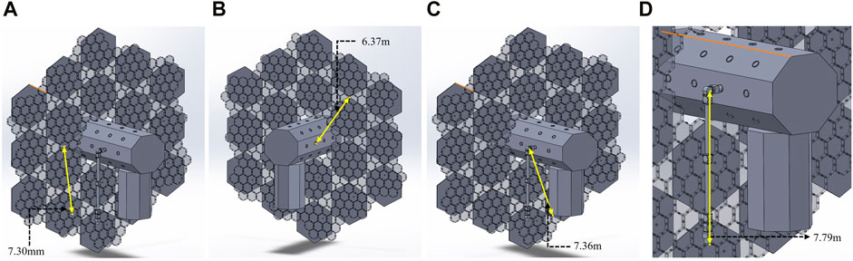
FIGURE 5. Distance between Bsc, Ssc and Truss Connector ports (A) Truss C8—PMS6_PMU1; (B) Bsc_C8—Truss C3; (C) E-Walker J2—Ssc lower edge; (D) E-Walker J2—E-Walker LEE2.
End-over-end walking robot
In this paper, the robotic architecture presented to facilitate the autonomous assembly of the
A top-level comparison between the state-of-the-art walking robot manipulators in space and the E-Walker space design is shown in Table 2. In terms of design comparison, the Canadarm2 has an offset around the elbow joint, which provides it with the capability to walk end-over-end, however, the connector ports have to be placed in a spacing equal to the joint offset to enable a straight-line motion. In comparison, the ERA and MOSAR have in-line elbow joint without an offset. However, as the two links are clamped onto the elbow joint on the sides, both the arms are limited of a full rotation around the elbow and end up in end-to-end walking. This results in an increased dependency on the roll joints of these robot manipulators, which is not recommended for a space mission. The E-Walker is an amalgamation of all the key features of the above-mentioned robotic arms, i.e., achieving end-over-end walking with an in-line elbow joint to achieve easy motion along a straight line without joint offset. For the earth-based design, the Climbot is a walking robot manipulator which has a similar elbow joint feature as the E-Walker. However, its workspace, redundancy and dexterity are limited due to the reduced number of joints (5 DoF).
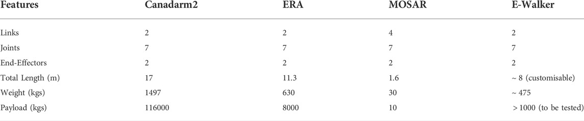
TABLE 2. Space-system comparison.
In comparison, the E-Walker prototype is dexterous with seven DoF and facilitates a modular design with customisable end-effectors. A comparison between Climbot and the E-Walker prototype design is enlisted in Table 3.
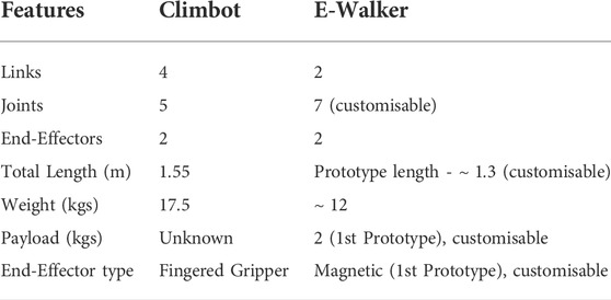
TABLE 3. Earth-analogue comparison.
The E-Walker’s capability to connect to static connector ports onboard the Bsc and Truss helps to cover a workspace much larger than its span. This enhanced reachability is an added benefit for assembly missions. In this paper, the E-Walker is assigned two key operations throughout the mission. These operations involve assembling PMSs using PMUs, thereafter, performing pick-and-place operations of the assembled PMSs onto their respective truss locations. The E-Walker would facilitate mobility around an attitude-stabilised Bsc, with a predefined motion that will not alter the attitude of the Bsc. This is contrary to the state-of-the-art concept of a space robot which requires additional effort in the Guidance, Navigation and Control unit. This is due to the complexities involved in maintaining attitude due to the non-linear dynamic coupling effects between the spacecraft platform and the fixed-to-base robotic manipulator (Flores-Abad et al., 2014).
The seven DoF E-Walker has three revolute joints, each in the shoulder and the wrist, and one DoF in the elbow joint. The dexterous symmetric design provides access to any part of the workspace (see Figure 1), satisfying the requirement
The initial design of the E-Walker considered a five DoF model, which included two revolute joints, each in the shoulder and wrist, one revolute joint in the elbow and two LEE on either end (Nair et al., 2020a). The five DoF E-Walker provided an insight into the minimum DoF required to realise the cyclic motion dynamics; this was a baseline design to carry out an end-over-end motion. This design met the requirement
Link design optimisation
Designing the E-Walker link requires optimising the link shape and dimensions prior to carrying out the SSA. An optimum link design should have the lowest mass and undergo minimal deflections under loading.
Link configuration
In this study, a solid tube, a hollow tube, and a rectangular beam were considered for the shape of the link (refer: Table 4). For tube shaped links,
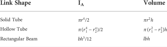
TABLE 4. Link shape, IA and volume equations.
Table 5 presents the dimensions of the three shapes to down select a single link based on their calculated parameters. To down select a single link shape. The space-qualified material, Aluminium 7075, with a density of
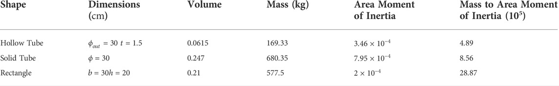
TABLE 5. Link parameters.
Link dimensions
Link configuration section presented the validation of selecting a hollow aluminium tube as the link shape. Therefore, to select the appropriate sizing of the link, different dimensions of a hollow tube were taken into consideration to conduct Finite Element structural analysis in Ansys. Table 6 shows four main sets (Set 1—Set 4) of link sizes considered for the analyses. Dimensions smaller than 20 cm were not considered as the links would have wirings running through their inner walls to support the actuators and other related electronics.
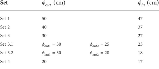
TABLE 6. E-Walker link dimension sets.
Link static structural analysis
The maximum deflection and stress on the different link sizes can be analysed by computing the deflection of a single link. If the E-Walker is assumed to be erect with LEE1 being fixed to the base, the maximum loading would be experienced by L1 due to J4-J7, L2, LEE2 and the payload. If LEE2 is fixed to the spacecraft platform, L2 would experience a similar load (J1-J4, L1, LEE1 and payload) due to the symmetry of the E-Walker. Therefore, if the design is validated for L1, then those results would be sufficient for L2. To carry out the link deflection tests, the E-Walker is assumed to be in the initial state of Phase 1, i.e., standing straight, carrying a payload of a PMS (
Modelling the Set 1 link produced minor deflection of
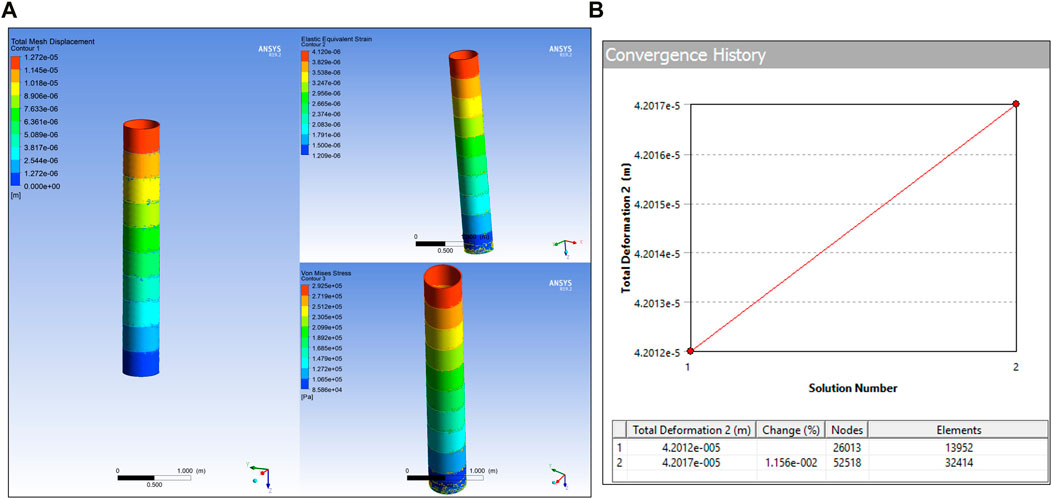
FIGURE 6. Link Set 1 (A) SSA; (B) Mesh convergence.
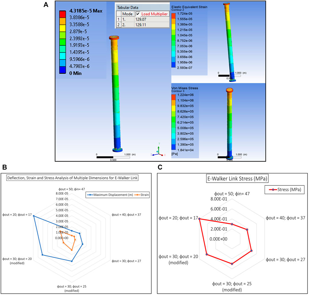
FIGURE 7. Link Set: (A) Ansys FEA of modified link; (B) Displacement and Strain Radar Chart of Link sets; (C) Stress Radar Chart of Link sets.
As seen from Figure 7C, a design with wider ends of
Latching end effector design analysis
The E-Walker consists of a Latching End-Effector (LEE) on either end to provide the required connection to the spacecraft platform and PMU connectors. The LEE is therefore subjected to loading conditions and requires further analysis to optimise the design (Figure 8). The LEE design in this paper has two ring features, one to latch onto the spacecraft platform (
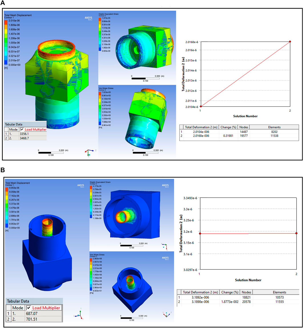
FIGURE 8. Latching end effector (A) large ring SSA; (B) small ring SSA.
For the SSA, one LEE of the E-Walker is assumed to be fixed on to the spacecraft and the other end is to be carrying the maximum payload of one PMS. For the larger ring, the maximum normal force would be applied when it bears the mass of the whole E-Walker carrying one PMS. The smaller ring experiences the maximum normal force due to the payload alone. Structural analysis of one LEE is enough due to the symmetry of the E-Walker. Referring to E-Walker’s initial position in Phase-1, a force of
Actuator selection
Selecting actuators for space missions revolves around understanding the dynamics of the system. The dynamical model of the E-Walker helps evaluate individual joint torque limits and the type of actuator needed for each joint.
Dynamic modelling of E-walker
Using the Euler-Lagrange equation (Spong, Hutchinson, and Vidyasagar 2006), the non-linear dynamic equation of the seven DoF E-Walker is given as:
where,
Here, the Jacobian matrix
During a space mission, due to the microgravity conditions, the effect of potential energy is usually neglected. However, near-less gravity plays an essential role in the control of robot dynamics in orbit and is taken into consideration in this paper. In Eq. 1, the gravity matrix
The maximum torque required by an E-Walker’s actuator can be computed with E-Walker completely stretched out by J2 and carrying a payload using a LEE. In this configuration, using Eq. 1 and considering E-Walker’s inertial parameters, the simulation was carried out with the E-Walker in its initial configuration of Phase 1, moving to the extreme position in
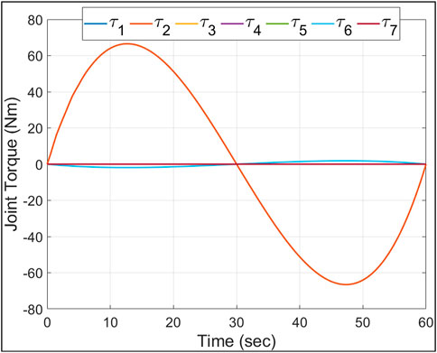
FIGURE 9. Joint two maximum torque.
E-walker modal analysis
Based on the E-Walker’s design optimisation in Link design optimisation, Latching end effector design analysis, and Actuator selection sections, the entire model was put under open-loop testing and no-load conditions in an ideal environment. As seen in Figure 10, the deflection is minimal. However, the challenge for the E-Walker is more severe as it has to move a PMS under the extreme environment in space and therefore requires frequency or modal analysis. The modal analysis in Ansys helps estimate the dynamic behaviour of the E-Walker when prone to different frequencies in the extremities of the space environment. The worst case performance of the E-Walker was evaluated in its most vulnerable position, i.e., with the arm completely stretched out about J2 with a maximum payload (
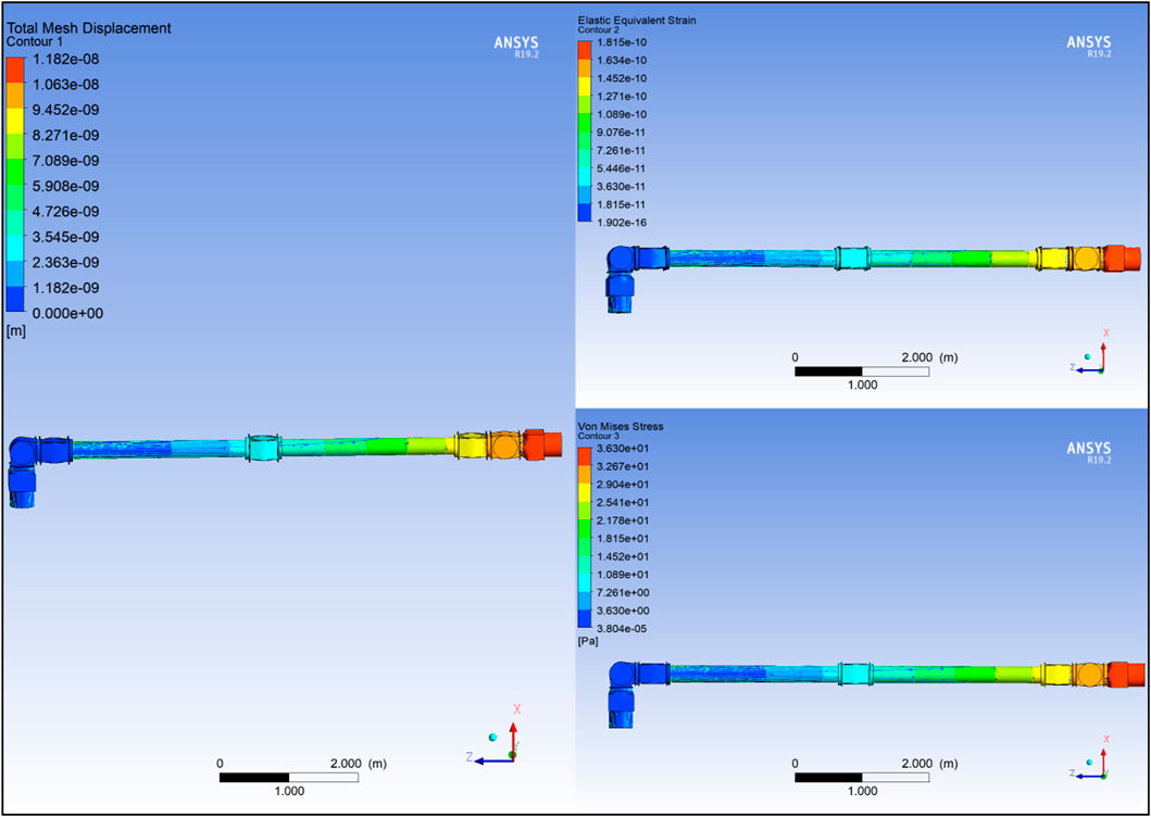
FIGURE 10. E-Walker SSA with no Payload.
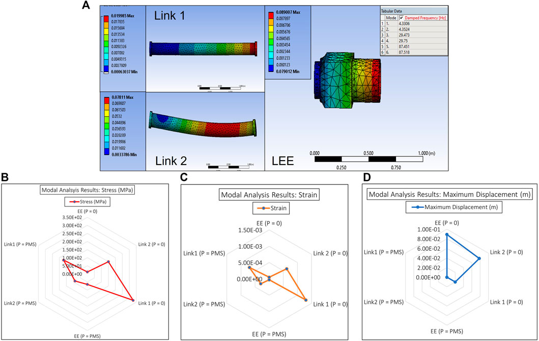
FIGURE 11. E-Walker Modal Analysis (A) Ansys Simulation of Links and LEE (B) Deflection analysis (C) Stress Analysis (D) Strain Analysis.
E-walker scaled-down Earth analogue design
Verifying the large-scale model of the E-Walker is near to impossible under Earth analogue conditions, given the high torque demands due to Earth’s gravitational pull and the limited microgravity environment test facility on the ground. Due to these reasons, a scaled-down prototype of the E-Walker is considered for fabrication to verify and validate tasks involving mobility and pick-and-place operations. The design engineering exercise similar to the one carried out in End-over-end walking robot is repeated for the prototype in Sections 4.1–4.4. The comparison of the full-scale E-Walker and its scaled-down Earth-analogue design helps understand the issues with scalability and the impact of Earth’s gravitational acceleration. Table 7 presents a summary of the design trade-offs of the full-scale E-Walker and its prototype. Detailed SSA and actuator selection methods are presented in the following subsections. Similar to the full-scale space design, it is significant to identify the design requirements specific to the E-Walker’s scaled-down prototype (
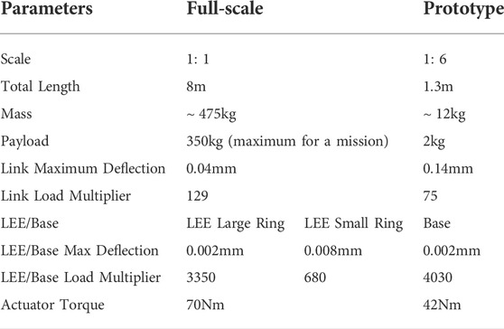
TABLE 7. E-walker full scale and prototype comparison.
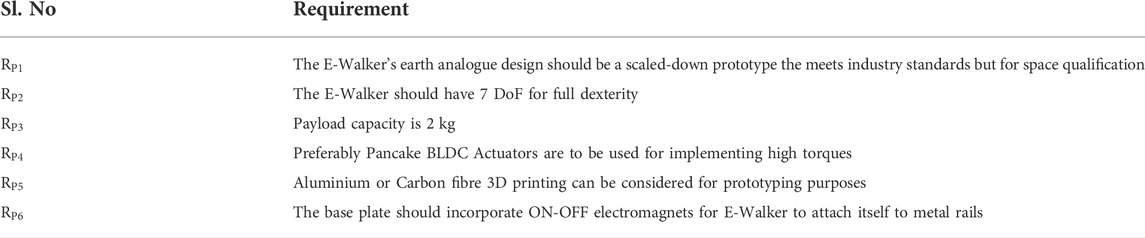
TABLE 8. E-walker prototype requirement list.
Bending moment, stall torque and actuator selection
A similar FEA-based analysis used in End-over-end walking robot design can be used to optimise the link design for the scaled-down prototype. Figure 12 helps identify a general equation to calculate the bending moment and the corresponding torque needed to traverse a desired trajectory. Considering the actuators and payload of a given dimension, Figure 12A shows the Bending Moment (BM) for the links of the seven DoF E-Walker. Corresponding to this worst-case configuration, L1 will experience a larger bending moment than L2. The symmetrical design of the E-Walker suggests that evaluating the bending moment on L1 alone at the stretched condition is sufficient to get a conclusive estimate of the maximum twist experienced.
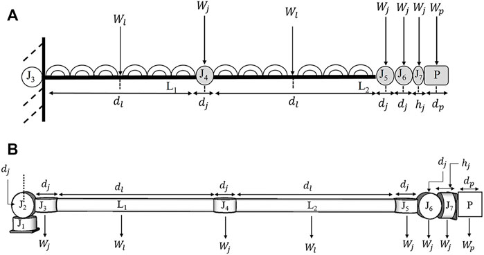
FIGURE 12. E-Walker Configuration (A) To calculate Bending Moment on L1 (B) To calculate Stall Torque on J2.
The links, actuators and payload are considered to have uniformly distributed load, with its weight considered to be concentrated at its centre of mass. From Figure 13, the following parameters are used to evaluate the
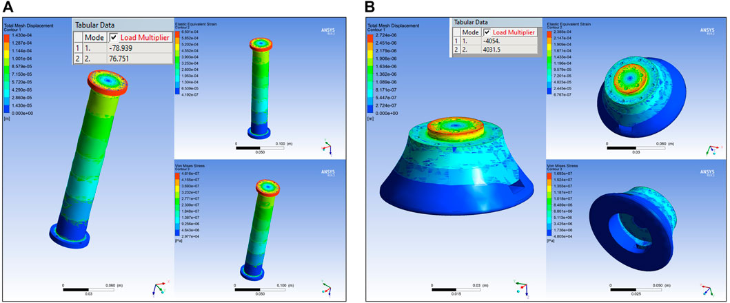
FIGURE 13. E-Walker prototype ansys FEA (A) Link (B) Base plate.
The maximum stall torque is estimated considering that all the actuators are of the same specification, and the E-Walker has to implement motion using either of its ends whilst carrying a
Based on Eq. 4 and Eq. 5, two case studies were carried out for different actuators available commercially (R100 KV90 2022; RMD-X8 Pro V2 2020; AK80-80 2022). In this research, a bespoke design of an using industrially available motors, gears, and encoders were not considered, given the compatibility issues, assembly costs and lead time. The RMD and AK series actuators had a diameter range between 5 and 10 cms. Therefore, a 5 cm and a 10 cm actuator is used to evaluate the range of BM and ST to carry a 2 kg payload (
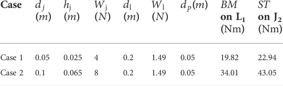
TABLE 9. Case Studies for E-Walker prototype design.
Link design optimisation and static structural analysis
Similar to the link design optimisation in End-over-end walking robot design, Table 10 shows the dimension sets considered for SSA. An optimal design reference was set for the links not to bend more than
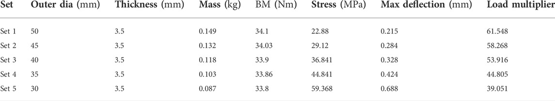
TABLE 10. Comparison of design parameters for different link dimensions.
Base plate design analysis
E-Walker’s prototype has a base plate equipped with on-off electromagnets on either end to fix itself on metallic structures and carry payloads (Electromagnet 2022). The maximum load on the base plate would be experienced when the E-Walker is erectly carrying the payload (
Mission concept of operations
A detailed feasibility analysis was carried out in a previous publication (Nair et al., 2020b), where a potential mission scenario, namely Mission Scenario 2b, was shortlisted after a trade-off analysis of eleven mission scenarios. A maximum of four E-Walkers were considered to carry out the assembly of the 25 m LAST. The analysis took into consideration the mission cost, lifting mass, net power requirements, control and motion planning complexity. This paper presents Mission Scenario 2b, which involves only two E-Walkers, namely EW1 and EW2 to carry out the in-orbit assembly of the 25 m LAST (Figure 14A). The mission ConOps provide an insight into task-sharing and co-manipulation with the collaborative operation between the two E-Walkers. This mission concept facilitated by two E-Walkers could facilitate futuristic LAST assembly missions with much larger apertures of 50 m or 100 m.
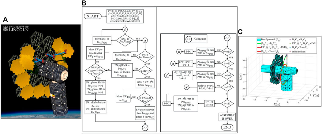
FIGURE 14. Mission scenario 2b: (A) Artistic illustration (B) flow chart (C) simulated trajectory.
Mission Scenario 2b involves both the E-Walkers sharing equal responsibilities in the assembly process. The tasks are split into assembling the PMS using the PMUs and performing pick-and-place operations to place the assembled PMSs to assemble the 25 m PM. To undertake the assembly, each of the E-Walkers is initially assigned one-half of the truss. This paper considers EW1 to take up the responsibility of the left half of the truss, whereas EW2 is responsible for the right half. The E-Walker’s reach is considered large enough to attend to the inner-ring assembly (positions 1–6) by staying on the Bsc. For the outer-ring assembly (positions 7–18), the E-Walkers will move to pre-designed connector points on the truss.
For a quick and efficient assembly, the operation is carried out in two modes. In Mode 1, both the E-Walkers collaborate to assemble a PMS, using the PMUs stored in the Ssc, in the inner ring of the truss. Once a PMS is assembled, one E-Walker steps onto the respective connector point on the truss (EW1 for the left-half and EW2 for the right-half) to pick and place the assembled PMS onto the respective outer-ring positions. Considering an operation where EW1 moves onto a left-half connector point on the truss to place a PMS, EW2 will begin assembling a new PMS while EW1 is away. Once EW1 places the PMS, it climbs back onto the Bsc to assist EW2 with the ongoing PMS assembly. For the right-half assembly, the roles of the E-Walkers are switched. Mode 1 of operation sees a majority of the outer ring being assembled.
Mode two of the assembly operation involves both the E-Walkers taking up individual responsibilities to assemble the PMS and to perform the pick-and-place operation in their respective halves. This is with the intent to utilise the E-Walker’s walking capability and reduce the overall sizing of the E-Walker. Additionally, each of the E-Walker will assemble PMSs simultaneously in the inner ring. The E-Walkers can attend to their respective halves in the inner ring from the Bsc itself. In Mode 2, both the E-Walkers collaborate to work independently and simultaneously, resulting in a faster assembly.
Assembly constraints and strategy
The LAST mission poses a few constraints to the E-Walker for an efficient assembly. For example, the E-Walker should maintain a clearance of 0.5–1 m from the assembled PMSs to reduce the chances of any collision. Additionally, while assembling or placing the PMSs, the E-Walker should make sure the task is not being carried out in an in-zone mirror position. Therefore, it is understood that the E-Walker has to be outside the zone of assembly at all times. A few strategies for assembly that takes into account these constraints are:
1) The assembly process can begin with the E-Walkers assembling the PMSs using the PMUs stored in the Ssc. Realising the fact that the E-Walkers have a reach to assemble the inner-ring positions from the Bsc, the assembly of the PMSs can be initially conducted on a certain inner-ring position. This allows the E-Walkers to walk around freely between the Bsc and truss.
2) The outer-ring positions can be filled in first. The assembled PMS in the inner ring can then be placed on to an outer ring position by an E-Walker moving onto the respective connector point based on their assigned halves. Assemble the outer ring mirrors first to allow the E-Walker to walk around the truss during the assembly process.
3) The mode of operation can be switched when a situation arises i.e., when the independent task execution of the E-Walkers in their assigned halves can help with a quick and efficient assembly.
4) Once the outer ring is completely assembled, the E-Walkers can climb back onto the Bsc to fill in the inner ring positions.
Flow chart of assembly process (mission scenario 2b)
The flowchart uses the following abbreviations:
Bsc - Base Spacecraft; Bsc_C - Base Spacecraft Connector; Cb - Connector point on truss; Ⓐ - assembles/assembling; PMS - Primary Mirror Segment; EW- End-Over-End Walker; Pos - Position.
The mirror positions with their inner and outer ring positions and the corresponding connector points on the truss can be recalled from Figure 3. The connector point numberings on the Bsc can also be understood from Figure 3. With the information on Mission Scenario 2b provided in Mission concept of operations (ConOps), a flowchart is presented in Figure 14B, which provides more in-depth insight into the mission ConOps. The terms used are:
a—In use Connector number array on Bsc; b - In use Connector number array on Truss.
mode—select the mode of operation.
mode 1—where EW1 and EW2 work together.
mode 2—EW1 and EW2 work parallelly on the left half and right half mirrors. p2l and p2r mirror arrays would be assembled in mode 2.
p'—Array of Initial Mirror position on Truss
p1—Array of outer-ring mirror positions to be assembled during mode 1
p2l—Array of final mirror positions to be assembled by EW1 on left-half of the truss–mode 2.
p2r—Array of final mirror positions to be assembled by EW2 on right-half of the truss (Positions in sequence: 8, 4, 3, 2)—mode 2.
c—PMS counter; m—array index of a; n—array index of b; i'—array index of p'; k—array index of c;
i—array index of p, provides insight into the number of assembled PMS.
It is to be noted that the above-mentioned variables m, n, i, i' and k start from 1.
d—Array of E-Walker Numberings; m - array index of a; n - array index of b; i1—array index of p2l
i2—Array index of p2r; l—Array index of d
Mission scenario 2b analysis
The assembly process of the 25 m LAST in the flowchart for Mission Scenario 2b begins with EW1 and EW2 taking their positions on their Bsc connector ports. EW1 takes a position on Bsc_C8 and EW2 on Bsc_C14. Positioning the E-Walkers on two sides of the Bsc helps with their move onto the truss connector ports in the respective halves. Now, the truss positions can be filled in with the assembled PMS from either half of the truss. In this paper, the assembly of the right-half outer ring of the truss is considered first. The positions of the truss are filled in a specific sequence based on the positions shown in Figure 2. The mission has two modes of operation to carry out the assembly.
The mode is initially set to 1 suggesting the collaborative working of both the E-Walkers. During mode 1, both the E-Walkers begin assembling the PMS on the inner-ring truss position 4, using the PMUs stored in the Ssc. Throughout the operation, the PMUs are considered to be readily available. Once the first PMS is assembled, EW2 moves onto C5 on the truss. EW2 then picks the assembled PMS from position four and places it on position 13, filling the first position of the 25 m LAST. While EW2 is performing the pick-and-place operation, EW1 starts assembling the second PMS. Post placing the first PMS, EW1 moves onto the Bsc to assist EW1 with the assembly of the second PMS. Positions 11 and 10 are filled similarly as seen with the first PMS, completing the placement of three PMSs. Thereafter, the same process is repeated to fill in positions 12 and 9, with EW2 moving onto C4 as position 12 is in-zone of C5. Now, a majority of the right-half outer ring is filled in.
To assist with the assembly of the left-half outer ring, the roles of the E-Walkers are switched. EW1 and EW2 assist with the assembly of the PMS, while EW1 now has an added responsibility to place the assembled PMSs by moving onto C8 on the truss. C8 helps the EW1 fill positions 14, 15, 16, 17 and 18 to successfully complete the placement of ten PMSs. Similar to the right-half assembly, EW2 continues to assemble a new PMS while EW1 is placing the previously assembled PMS. Once the assembled PMS is placed, EW1 climbs back onto the Bsc to assist EW2 with the assembly of the new PMS.
The mode of operation now switches to mode 2. With eight positions left to be filled, two positions are in the outer ring, while six positions are in the inner ring. In mode 2, EW1 and EW2 have individual responsibilities of assembling the PMS and perform the pick-and-place operation in their respective halves. To fill out the outer ring, EW1 assembles a PMS in inner-ring position five while EW2 assembles a PMS in position 3. Post assembling the PMS, EW1 moves onto C6 and EW2 to C2 on the truss. EW1 moves the assembled PMS from position five to position 7, while EW2 places the PMS on position 8. This step is well represented in Figure 14A. This marks the successful assembly of the outer ring of the 25 m PM. For the inner-ring assembly, EW1 and EW2 move onto Bsc and performs a simultaneous assembly of the PMSs on each half of the truss. While EW1 assembles the inner ring positions 5, 6 and 1, EW2 completes the assembly by filling up positions 4, three and 2. The assembly of the 18 PMSs marks the successful completion of the 25 m LAST.
The systematic assembly presented eliminates the risks of the E-Walker colliding with the mirror modules by avoiding in-zone mirror positions. This helps in satisfying the top-level requirement R4 of the E-Walker. Requirements
Mission trajectory tracking
Figure 14C shows the trajectory tracking of EW1 during the Mission Scenario 2b assembly process in a simulated environment. Trajectory 1 represents EW1’s motion from Bsc_C11 to Bsc_C8. The motion is quite similar to Phase-1 of Cycle-1. Considering joint 1 is fixed at Bsc_C11, the motion of the EE attached to q7 is tracked to reach Bsc_C8. This satisfies the initial condition check for EW1 in the assembly process, depicted in the flow chart. Trajectory two represents the tracking of joint 1’s motion to fetch a PMU from the Ssc. During this motion, joint five is locked at Bsc_C8. The third trajectory portrays a common motion for EW1 during the operation in Mode 1, where EW1, with joint five fixed to Bsc_C8 moves onto C8, on the truss, to pick and place the assembled PMS in the relevant truss position on the left half of the truss.
Conclusion and future research
This paper introduced the design and feasibility of a walking space manipulator for in-situ robotic assembly of a
The E-Walker presented would be able to extend the mission lifecycle by carrying out routine maintenance and servicing missions post assembly. The E-Walker design shown is versatile, and it is a candidate robot for future planetary and orbital missions. In addition to the full-scale design, a scaled-down (
Future research includes finalising the design specifications of the true-scale E-Walker for the 25 m LAST mission. Additionally, an Earth-based small-scale E-Walker prototype is under development for further hardware-in-loop experimentation. This prototype can then be tested with space-qualified robust controllers, like the Proportional-Integral-Derivative-Computed-Torque-Controller or the H∞ controller for precise joint tracking under external disturbances and parametric uncertainties. Given the huge commercial interest in this topic, Space agencies and industries have developed their road maps for orbital robotics missions. The LAST mission and the E-Walker model have also drawn commercial and scientific attention. Over the next 5–10 years, it is envisaged that researchers and industries will carry out further development to assess E-Walker’s feasibility. These include prototyping an E-Walker for a precursor mission involving a 2.5m/5 m LAST. The E-Walker’s capability for assembling the secondary mirror, truss modules and baffles is not yet realised.
Data availability statement
The original contributions presented in the study are included in the article/Supplementary Material, further inquiries can be directed to the corresponding author.
Author contributions
MN—Lead researcher; MR—PhD Supervisor and editorial support; MP—Simulation and editorial support.
Funding
This research is fully funded by the University of Lincoln as part of the PhD process of MN.
Acknowledgments
We would like to thank the UK space In-Orbit Servicing and Manufacturing working group, comprising several Space industries, for their constant encouragement and commercial interest in orbital robotic missions. Thanks to Steve Eckersley at Surrey Satellite Technology Ltd. for the advice on mission requirements.
Conflict of interest
The authors declare that the research was conducted in the absence of any commercial or financial relationships that could be construed as a potential conflict of interest.
Publisher’s note
All claims expressed in this article are solely those of the authors and do not necessarily represent those of their affiliated organizations, or those of the publisher, the editors and the reviewers. Any product that may be evaluated in this article, or claim that may be made by its manufacturer, is not guaranteed or endorsed by the publisher.
References
Baiocchi, D., and Stahl, H. P. (2009). “Enabling future space telescopes: Mirror technology review and development roadmap,” in The astronomy and astrophysics decadal survey (Astro2010).
Brooks, S., Godart, P., Backes, P., Chamberlain-Simon, B., Smith, R., and Karumanchi, S. (2016). An untethered mobile limb for modular in-space assembly. In Proc. 2016 IEEE Aerospace Conference, 1–9. USA: MT. doi:10.1109/aero.2016.7500878
Burrows, Christopher J. (1991). “Hubble space telescope optics: Problems and solutions,” in Proceedings Volume 1494, Space Astronomical Telescopes and Instruments, Orlando, FL. Editors P. Y. Bely, and B. B. Breckinridge, 528–533. doi:10.1117/12.46708
Cruijssen, H. J., Ellenbroek, M., Henderson, M., Petersen, H. R., Verzijden, P., and Visser, M. (2014). The European robotic arm: A high-performance mechanism finally on its way to space. NASA Technical Reports Server (NTRS). [Online]. Available: https://ntrs.nasa.gov/api/citations/20150004070/downloads/20150004070.pdf (Last Accessed: September 03, 2022).
Culbertson, F. (2003). “Operating the ISS: A world-wide team effort,” in Proc. AIAA international air and space symposium and exposition: The next 100 years (Reston, Virigina: American Institute of Aeronautics and Astronautics). doi:10.2514/6.2003-2701
Dalla, V. K., and Pathak, P. M. (2019). Power-optimized motion planning of reconfigured redundant space robot. Proc. Institution Mech. Eng. Part I J. Syst. Control Eng. 233 (8), 1030–1044. doi:10.1177/0959651818814133
Deremetz, M., Letier, P., Grunwald, G., Roa, M. A., Brunner, B., Ferrán Cfiuentes, A., et al. (2021). “MOSAR-WM: Integration and test results of a relocatable robotic arm demonstrator for future on-orbit servicing missions,” in Proc. 2021 international astronautical congress (IAC2021). Cyberspace Edition (Dubai.
Dursun, T., and Soutis, C. (2014). Recent developments in advanced aircraft aluminium alloys. Mater. Des. (1980-2015) 56, 862–871. doi:10.1016/j.matdes.2013.12.002
Fazekas, A. (2020). Top 5 space station repair spacewalk dangers. National Geographic Society Newsroom. 2020. [Online]. Available: https://blog.nationalgeographic.org/2013/12/20/top-5-space-station-repair-spacewalk-dangers/ (Last Accessed: September 03, 2022).
Flores-Abad, A., Ma, O., Pham, K., and Ulrich, S. (2014). A review of space robotics technologies for on-orbit servicing. Prog. Aerosp. Sci. 68, 1–26. doi:10.1016/j.paerosci.2014.03.002
Garzón, M. A. R., Nottensteine, K., Wedler, A., and Grunwald, G. (2017). “Robotic technologies for in-space assembly operations,” in Proc. 14th symposium on advanced space technologies in robotics and automation (ASTRA), 20-22 june 2017 (Leiden, Netherlands.
Gobin, S.UK Farnell (2022). 58-0250 24 VDC electromagnet. [Online]. Available: https://hk.element14.com/stephenson-gobin/58-0250-24-vdc/electromagnet-type-58/dp/7200924 (Last Accessed: September 03, 2022).
Gook, D. G. (2015). The Canadian designed and built SPAR/MDA canadarms - Canada’s contribution to space exploration. [Online]. Available: https://documents.techno-science.ca/documents/CASM-Aircrafthistories-SparMDACanadarms.pdf (Last Accessed: September 03, 2022).
Hughes, T. J. R., Cottrell, J. A., and Bazilevs, Y. (2005). Isogeometric analysis: CAD, finite elements, NURBS, exact geometry and mesh refinement. Comput. Methods Appl. Mech. Eng. 194 (39–41), 4135–4195. doi:10.1016/j.cma.2004.10.008
Lee, Ni, Paul, B., Joel, B., Pellegrino, S., Fuller, C., Hogstrom, K., Kennedy, B., et al. 041207 (2016). Architecture for in-space robotic assembly of a modular space telescope. J. Astronomical Telesc. Instrum. Syst. 2 (4). doi:10.1117/1.jatis.2.4.041207
Letier, P., Yan, X-T, Deremetz, M., Bianco, A., Grunwald, G., Roa, M. A., et al. (2019). “Mosar: Modular spacecraft assembly and reconfiguration demonstrator,” in Proc. ASTRA 2019 symposium (Netherlands: Noordwijk), 27–28.
Lockwood Optics (2020). Ritchey-chretien cassegrain telescope design equations. [Online]. Available: http://www.loptics.com/ATM/ (Last Accessed: September 03, 2022).
Nair, Manu H., Saaj, C. M., Esfahani, A. G., Nanjangud, A., Eckersley, S., and Bianco, P. (2020). “In-space robotic assembly and servicing of high-value infrastructure,” in Proc. 2020 international astronautical congress (IAC2020). Cyberspace Edition (Dubai.
Nair, M. H., Saaj, C. M., Adlen, S., Esfahani, A. G., and Eckersley, S. (2020). “Advances in robotic in-orbit assembly of large aperture space telescopes,” in Proc. 15th international symposium in artificial intelligence, robotics and automation in space (i-SAIRAS) oct 2020 (US: Pasadena).
Nair, M. H., Saaj, C. M., and Esfahani, A. G. (2020). “Modelling and control of an end-over-end walking robot,” in Proc. 21st towards autonomous robotic systems (TAROS) conference, online, 16 september 2020 (Nottingham, UK. doi:10.1007/978-3-030-63486-5_15
Nanjangud, A., Blacker, P. C., Young, A., Saaj, C. M., Underwood, C. I., Eckersley, S., et al. (2019). “Robotic architectures for the on-orbit assembly of large space telescopes,” in Proc. 15th advanced space technologies in robotics and automation (ASTRA) 2019 symposium, 27-28 may 2019 (Netherlands: Noordwijk).
Nanjangud, A., Underwood, C. I., Bridges, C. P., Saaj, C. M., Eckersley, S., Sweeting, M., et al. (2019-25 October 2019). “Towards robotic on-orbit assembly of large space telescopes: Mission architectures, concepts, and analysis,” in Proc. 70th international astronautical congress (IAC) (Washington DC, USA, 21.
NASA (2020). Hubble makes surprising find in early universe. [Online]. Available: https://www.nasa.gov/feature/goddard/2020/hubble-makes-surprising-find-in-early-universe (Last Accessed: September 03, 2022).
Nelson, A., Koizumi, K., and Uzo-Okoro, E. (2022). Space servicing, assembly, and manufacturing interagency working group of the national science & technology council. Executive Office of the President of the United States, April 2022. [Online]. Available: https://www.whitehouse.gov/wp-content/uploads/2022/04/04-2022-ISAM-National-Strategy-Final.pdf (Last Accessed: September 03, 2022).In-space servicing, assembly, and manufacturing national strategy
Nelson, J., Mast, T., and Chanan, G. (2013). Segmented mirror telescopes BT - planets, stars and stellar systems: Volume 1: Telescopes and instrumentation. Dordrecht: Springer Netherlands, 99–136.
Oegerle, W. R., Purves, L. R., Budinoff, J. G., Moe, R. V., Carnahan, T. M., and Evans, D. C. (2006). “Concept for a large scalable space telescope: In-space assembly,”In Proceedings Volume 6265, Space Telescopes and Instrumentation I: Optical, Infrared, and Millimeter, Orlando, FL. Editors John C. Mather, and Howard A. MacEwen, 62652C. doi:10.1117/12.672244
Raffo, G. V., Ortega, M. G., and Rubio, F. R. (2011). Nonlinear H∞ controller for the quad-rotor helicopter with input coupling*. IFAC Proc. Vol. 44 (1), 13834–13839. doi:10.3182/20110828-6-it-1002.02453
Robot Shop (2020). RMD-X8 Pro V2 brushless DC servo motor 1:9, MC300A. Available at: https://Www.Robotshop.Com/Uk/My-Actuator-Rmd-X8-pro-v2-Brushless-Dc-Servo-Motor-19-Mc300a.Html. 2020.
Rognant, M., Cumer, C., Biannic, J., Roa, M. A., Verhaege, A., and Bissonnette, V. (2019). “Autonomous assembly of large structures in space: A technology review,” in Proc. 8th European conference for aeronautics and aerospace sciences (EUCASS).
Satellite Applications Catapult (2020). In-space services - a major opportunity for the UK - satellite applications Catapult. https://sa.catapult.org.uk/in-space-services-a-major-opportunity-for-the-uk/ (Last Accessed: September 03, 2022).
Space Actuators (2017). Space sector brochure, moog components group. Moog. Available at: https://Www.Moog.Com/Products/Actuators-Servoactuators/Space.Html February, 2017).
Space Robotics (2022). Aerospace, harmonic drive SE. [Online]. Available: https://Harmonicdrive.de/En/Applications/Aerospace. 2022 (Last Accessed: September 03, 2022).
T-Motor (2020). AK80-80. [Online]. Available: https://Store.Tmotor.Com/Goods.Php?Id=1032 (Last Accessed: September 03, 2022).
T-Motor (2022). R100 KV90. [Online]. Available: https://store.tmotor.com/goods.php?id=1032 (Last Accessed: September 03, 2022).
Thirsk, R., Kuipers, A., Mukai, C., and au, fnm 2009). The space-flight environment: The international space station and beyond. Can. Med. Assoc. J. 180 (12), 1216–1220.doi:10.1503/cmaj.081125
Yisheng Guan, Y., Li Jiang, L., Haifei Zhu, H., Xuefeng Zhou, X., Chuanwu Cai, C., Wenqiang Wu, W., et al. (2011). Climbot: A modular bio-inspired biped climbing robot. IEEE/RSJ International Conference on Intelligent Robots and Systems. –1478. [Online]. Available:. doi:10.1109/IROS.2011.6094406Last Accessed: September 03, 2022)Climbot: A modular bio-inspired biped climbing robot
Younger, Mandy, and Eckelmeyer, Kenneth (2007a). “Aluminum alloys for satellite boxes : Engineering guidelines for obtaining adequate strength while minimizing residual stresses and machining distortion,” in Technical report (Albuquerque, NM, and Livermore, CA, United States: OSTI.GOV). doi:10.2172/922072
Keywords: in-space assembly, large aperture space telescope, mission requirements, assembly challenges, walking robotic manipulator, design engineering, finite element analysis
Citation: Nair MH, Rai MC and Poozhiyil M (2022) Design engineering a walking robotic manipulator for in-space assembly missions. Front. Robot. AI 9:995813. doi: 10.3389/frobt.2022.995813
Received: 16 July 2022; Accepted: 12 September 2022;
Published: 14 October 2022.
Edited by:
Xiaofeng Wu, The University of Sydney, AustraliaReviewed by:
Qiang Shen, Shanghai Jiao Tong University, ChinaAbdulHalim Jallad, United Arab Emirates University, United Arab Emirates
Copyright © 2022 Nair, Rai and Poozhiyil. This is an open-access article distributed under the terms of the Creative Commons Attribution License (CC BY). The use, distribution or reproduction in other forums is permitted, provided the original author(s) and the copyright owner(s) are credited and that the original publication in this journal is cited, in accordance with accepted academic practice. No use, distribution or reproduction is permitted which does not comply with these terms.
*Correspondence: Manu Harikrishnan Nair, [email protected]